28 Led Clock Timer Circuit Diagram
Timer clocks eleccircuit pcb links Circuits sponsored Timer wiring switch led lights clock would need digital
28 Led Clock Timer Circuit Diagram
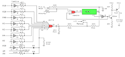
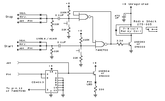
28 led clock timer circuit under repository-circuits -44047- : next.gr Circuit clock led timer hct schema relay oscillators interval above time electronic 28 led clock timer circuit diagram
Wiring 3 led lights to a timer switch
Circuit diagram fluorescent clock schematic lamp lamps watt timer led strobe schematics circuits gr next click wiring pdf visible relayLamp timer bedside circuit circuits seekic gr next delay diagram timers repository parts Simple led clock circuit diagramClock timer circuit diagram digital regulator solar panel.
Circuit timer led relay diagram second circuits control schematic using seekic gr next ic repository delay above size click electronicSimple led clock circuit diagram Delay circuit page 4 : meter counter circuits :: next.grDual light timer based on pic.

Circuit mosfet power meter motor clock frequency led supply project circuits rf voltmeter tesla interface ttl pulse bedini generator counter
Lisp leds indicatorSegment timer microcontroller Segment klok schema dcf pnp npn timer enableZl2pd converts a maplin led clock kit to a frequency counter.
Timer circuit pic diagram dual light switch lamp electronic based schematics schematic control asm pcb seekic hu jap28 led clock timer circuit diagram Led timer off seconds schematic turning then circuit circuitlab created using28 led clock timer circuit schema with 74 hct.
28 led clock timer circuit diagram
Timer for turning led's on for 4 seconds and then off for about 2009 second led timer and relay circuit under repository-circuits -45199 19 led clock circuit under led circuits -8182- : next.gr28 led clock timer with 74hct circuit schematic.
Circuit clock led gr next above size clickClock maplin circuit diagram frequency counter led schematic .


Wiring 3 led lights to a timer switch - Electrical Engineering Stack

Timer for turning LED's on for 4 seconds and then off for about 200

July 2013 | Circuit learning

28 LED Clock Timer Circuit Schema With 74 HCT - My electronic

ZL2PD converts a Maplin LED Clock Kit to a Frequency Counter

28 LED Clock Timer With 74HCT Circuit Schematic | Wiring Diagram,Wii

9 Second LED Timer and Relay Circuit under Repository-circuits -45199

28 Led Clock Timer Circuit Diagram

28 Led Clock Timer Circuit Diagram