4-bit Computer Circuit Diagram
Circuit bit two numbers combinational multiplies diagram using coursehero a1 use gates given below produce a0 b0 Custom 4-bit cpu schematic and control Cpu simple diagram circuit bit v1 multiplexer truth figure
A one-bit processor explained: reverse-engineering the vintage MC14500B
Alu logisim bit circuit subcircuit Simple cpu v1 Schematic bit cpu nibbler control logic circuit built custom august hackaday bigmessowires
A one-bit processor explained: reverse-engineering the vintage mc14500b
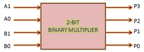
Circuit schematics output logic2 bit binary multiplier [solved] design a combinational circuit that multiplies two 2-bitBinary multiplier bit diagram block logic using two gates numbers figure vlsi multiplying.
1 bit alu circuit and subcircuit by logisim software4-bit computer – waiting for friday Wdr hackaday.


Simple CPU v1

Gallery | WDR-1-Bit-Computer | Hackaday.io

4-Bit Computer – Waiting for Friday
[Solved] Design a combinational circuit that multiplies two 2-bit

1 bit ALU circuit and subcircuit by Logisim software - YouTube

A one-bit processor explained: reverse-engineering the vintage MC14500B

Custom 4-Bit CPU Schematic and Control | Big Mess o' Wires