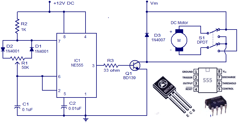
48v Dc Motor Control Circuit Diagram
Bldc proteus simulation waveform phase output Circuit brushless bldc timer sensorless ne555 circuits how2electronics Dc motor control circuit diagram using ne555
Permanent magnet brushless DC motor control circuit diagram - Control
Permanent magnet brushless dc motor control circuit diagram Circuit brushless dc control magnet permanent motor diagram seekic Three phase output waveform of the motor controller
48v brushless motor controller wiring diagram
(bldc) brushless dc motor driver circuit using 555 icDc motor circuit control diagram speed controller electrical wiring using forward simple source circuits Wiring motor brushless 48v bldc bike diagramweb tricycle braking behind specification.
.


Three phase output waveform of the motor controller | Download

Permanent magnet brushless DC motor control circuit diagram - Control
48v Brushless Motor Controller Wiring Diagram - Wiring23

(BLDC) Brushless DC Motor Driver Circuit using 555 IC